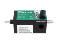
KHG 10
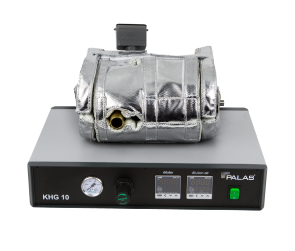
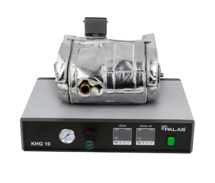
The KHG 10 series of heatable dilution systems builds upon the VKL series ejector principle. In addition to the advantages of the VKL series, the KHG series dilution system is configured to be heatable to 150 °C (optionally up to 200 °C) and is additionally pressure-resistant up to 10 bar pressure. Isothermal and isobaric dilution can therefore be achieved. With the KHG system, both the compressed air supplied and the dilution system are self-heated.
The welas® KHG 10 series of dilution systems can reduce the concentration of aerosols by the dilution factor 1:10 under isothermal conditions, also of very highly concentrated aerosols, in a defined and reliable way.
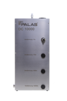
Dilution factors of up to 1:100,000 are achieved by cascading several KHG 10 systems.
Operation principle
Dilution system is heatable and pressure-resistant up to 10 bar
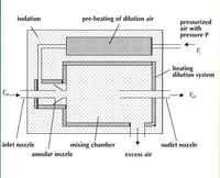
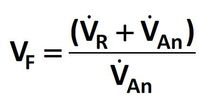
Particle-free air with the volume flow VR circulates through an annular passage around the suction nozzle. Thus, according to Bernoulli, a volume flow VAn is generated at the suction nozzle. The volume flow VR is heated to the required temperature of the aerosol to be measured using cartridge heaters, such that isothermal conditions prevail. The dilution factor VF is calculated according to the following formula:
Care has to be taken with the heatable system of the KHG 10 system that the entire measurement chain is configured to be isothermal to avoid condensation or evaporation effects with liquid aerosols.
VDI report no. 1973 from 2007 proved metrologically that a reproducible aerosol dilution is possible with the Palas® dilution systems down to VF 100,000.
Simple, functional test on-site (with the example of the VKL series)
With this simple test setup, the Palas® cascaded dilution systems can be checked by anyone:
Firstly a particle measurement is performed with one dilution step. Here it is essential that the aerosol concentration, e.g., lab air, to be measured does not exceed the coincidence limit (maximum detectable aerosol concentration). In the second step, the dilution step to be tested is connected in series (cascaded). To check the dilution factor of the test step (position 2), the total particle count from the measurement in position 1 is divided by the total particle count from position 2.
Experimental setup
Position 1: Lab air
Position 2: Lab air
The VKL 100 measures coincidence-free with the OPC; the VKL 10 is tested.
Measurement example
KHG measurement example 1
| Particle class in µm | Number Pos. 1 | Pressure - resistant up to 10 bar | Chemically resistant | Heatable up to ... °C | dpmax in µm | Compressed air 4 - 8 bar | Cascadable | Voltage |
|---|---|---|---|---|---|---|---|---|
| 0.2 | 151648 | < 5 | 115 V / 230 V | |||||
| 0.3 | 71604 | < 5 | 115 V / 230 V | |||||
| 0.5 | 4305 | < 5 | 115 V / 230 V | |||||
| 0.7 | 360 | x | 150 | < 20 | x | x | 115 V / 230 V | |
| 1.0 | 82 | x | x | 150 | < 20 | x | x | 115 V / 230 V |
| 2.0 | 16 | x | 200 | < 5 | x | 115 V / 230 V | ||
| 3.0 | 1 | x | 200 | < 5 | x | 115 V / 230 V | ||
| 5.0 | < 10 | x | 115 V / 230 V | |||||
| Sum | 228016 | < 20 | x | x | ||||
| VKL 10 E | 10 | x | < 20 | x | x | |||
| VKL 10 ED | 10 | x | x | < 20 | x | x | ||
| VKL 10 V | 10 | < 20 | x | x | ||||
| VKL 27 | 27 | < 10 | x | x | ||||
| VKL 100 | 100 | < 2 | x | x |
KHG measurement example 2
| Particle class in µm | Number Pos. 1 | Pressure - resistant up to 10 bar | Chemically resistant | Heatable up to ... °C | dpmax in µm | Compressed air 4 - 8 bar | Cascadable | Voltage |
|---|---|---|---|---|---|---|---|---|
| 0.2 | 15166 | < 5 | 115 V / 230 V | |||||
| 0.3 | 7290 | < 5 | 115 V / 230 V | |||||
| 0.5 | 524 | < 5 | 115 V / 230 V | |||||
| 0.7 | 65 | x | 150 | < 20 | x | x | 115 V / 230 V | |
| 1.0 | 21 | x | x | 150 | < 20 | x | x | 115 V / 230 V |
| 2.0 | 3 | x | 200 | < 5 | x | 115 V / 230 V | ||
| 3.0 | x | 200 | < 5 | x | 115 V / 230 V | |||
| 5.0 | 2 | < 10 | x | 115 V / 230 V | ||||
| Sum | 23071 | < 20 | x | x | ||||
| VKL 10 E | 10 | x | < 20 | x | x | |||
| VKL 10 ED | 10 | x | x | < 20 | x | x | ||
| VKL 10 V | 10 | < 20 | x | x | ||||
| VKL 27 | 27 | < 10 | x | x | ||||
| VKL 100 | 100 | < 2 | x | x |
Calculation of the dilution factor:
Provided the first measurement is not affected by a coincidence error and the dilution system under test is working (not soiled), a dilution factor of almost 10 is determined. If this should not be the case, there was possibly coincidence in measurement 1. In this case, the aerosol concentration has to be decreased or a further dilution step used. Another possibility would be that the dilution step to be tested is soiled. In this case, the device has to be cleaned and the test repeated.
Characteristics dilution systems
| Type | Dilution factor* VF | Pressure - resistant up to 10 bar | Chemically resistant | Heatable up to ... °C | dpmax in µm | Compressed air 4 - 8 bar | Cascadable | Voltage |
|---|---|---|---|---|---|---|---|---|
| DC 100 | 10, 100 | < 5 | 115 V / 230 V | |||||
| DC 1000 | 10, 100, 1000 | < 5 | 115 V / 230 V | |||||
| DC 10000 | 10, 100, 1000, 10000 | < 5 | 115 V / 230 V | |||||
| KHG 10 | 10 | x | 150 | < 20 | x | x | 115 V / 230 V | |
| KHG 10 D | 10 | x | x | 150 | < 20 | x | x | 115 V / 230 V |
| PMPD 100 | 100 | x | 200 | < 5 | x | 115 V / 230 V | ||
| PMPD 1000 | 1000 | x | 200 | < 5 | x | 115 V / 230 V | ||
| VDD 10 | 1 - 10 | < 10 | x | 115 V / 230 V | ||||
| VKL 10 | 10 | < 20 | x | x | ||||
| VKL 10 E | 10 | x | < 20 | x | x | |||
| VKL 10 ED | 10 | x | x | < 20 | x | x | ||
| VKL 10 V | 10 | < 20 | x | x | ||||
| VKL 27 | 27 | < 10 | x | x | ||||
| VKL 100 | 100 | < 2 | x | x |
Table 1: Technical characteristics of Palas® dilution systems
Benefits
Your special advantages
- The dilution systems from Palas® are characterized unambiguously. This is documented with a calibration certificate for each individual device
- The dilution steps deliver a temporally constant, representative dilution with the factors 10 and 100
- The dilution systems can be cascaded with the factors 100, 1,000, 10,000 and 100,000
- Low compressed air consumption, e.g. just 128 l/min with a dilution factor of 10,000 with four VKL 10 systems
- The dilution steps are combinable with all common particle counters.
- With a simple test set-up, these cascaded dilution systems can be checked by the users themselves.
- Isobaric dilution up to 10 bar overpressure / isothermal dilution up to 120 °C with the VKL 10 E, VKL 10 ED, KHG 10 and KHG 10 D dilution systems
- Simple functional test on-site
Applications
Individual solutions for various industries
- Dilution of hot aerosols, e.g., engine oil, DEHS, etc.
- Aerosol measurement technology: diesel exhaust gases, swarfs, coolant aerosols, weld smoke, oil droplets, test aerosols of filters, and inertial separators
- Separation efficiency determination with counting measuring methods, e.g., oil mist separators
- Hot gas filtration
- Measurement of isolators under pressure conditions
- Toxicology, e.g., testing of medical nebulizers/inhalation studies, etc.
Technical features
In detail
- Volume flow (clean air)
- 18 – 45 l/min (heatable until 150 °C)
- Volume flow (suction flow)
- 2 – 5 l/min
- Power supply
- 115 – 230 V, 50/60 Hz
- Isokinetic suction nozzles
- 0,6–1,6 l/min, 2–5 l/min, 4–10 l/min, 8–16 l/min, 28 l/min => 15–37 l/min
- Maximum particle size
- < 20 µm (for dusts)
- Thermodynamic conditions for dilution
- ≤ 400°C, ≤ 10 barg
- Compressed air supply
- 4 – 8 bar
- Dilution factor
- 1 : 10
- Special features
- Heatable until 150 °C, cascadable, chemical resistant
